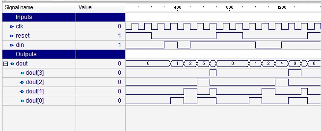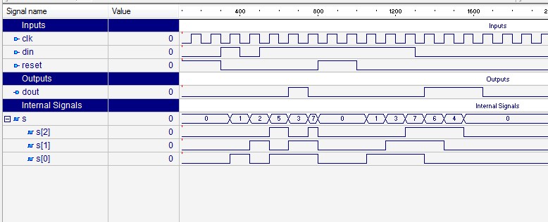

All these flip-flops are synchronous with each other since the same clock signal is applied to each flip flop. The circuit consists of four D flip-flops which are connected in a serial manner. The logic circuit given below shows a serial-in serial-out shift register. Since there is only one output, the data leaves the shift register one bit at a time in a serial pattern, thus the name Serial-In Serial-Out Shift Register. The shift register, which allows serial input (one bit after the other through a single data line) and produces a serial output is known as Serial-In Serial-Out shift register. Parallel In parallel Out shift register Serial-In Serial-Out Shift Register (SISO) –.Shift registers are basically of 4 types. The registers which will shift the bits to right are called “Shift right registers”.

The registers which will shift the bits to left are called “Shift left registers”. An n-bit shift register can be formed by connecting n flip-flops where each flip flop stores a single bit of data.

The bits stored in such registers can be made to move within the registers and in/out of the registers by applying clock pulses. Shift Register is a group of flip flops used to store multiple bits of data. The information stored within these registers can be transferred with the help of shift registers.
#PARALLEL INPUT SERIAL OUTPUT SHIFT REGISTER VHDL CODE SERIES#
It is a group of flip flops connected in series used to store multiple bits of data. A Register is a device which is used to store such information. N flip flops are to be connected in an order to store n bits of data. However, in order to store multiple bits of data, we need multiple flip flops.


 0 kommentar(er)
